Use the Spines analysis if you placed spines manually, or detected spines with AutoSpine (Neurolucida 11 or previous) or Neurolucida 360.
You can generate the Spine report and the Spine details report.
If you detected spines with Neurolucida 360, details are broken down into two reports:
![]() If you used markers for the spines, use the Individual Marker or Marker Totals analyses.
If you used markers for the spines, use the Individual Marker or Marker Totals analyses.
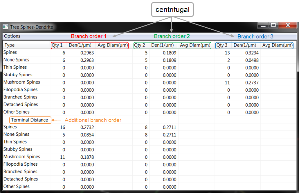 Reports the quantity, density, and average diameter of each spine class by centrifugal branch order.
If you selected additional branch orders for your analyses, additional data is displayed below the rows of data relative to the centrifugal branch orders.
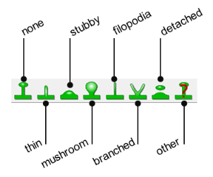
Refers to the class(es) used in Neurolucida to mark the spines.
[Quantity of spines on the segment]/[Length of the segment]
Average diameter of the spines on the segment.
Each tree selected for the analysis is assigned a unique number starting at 1.
Uses the Centrifugal branch order. See "About Branch Orders"
Refers to the class(es) used in Neurolucida to mark the spines.
Shortest path distance from the center of the spine head to the center of the dendrite.
Shortest path distance from the center of the spine head to the surface of the dendrite.
To determine the radius of the dendrite, subtract Length to Center and Length values.
Diameter of the spine head.
Sum of the lengths of the branch segments from the base of the spine to the beginning of the tree the spine is attached to. 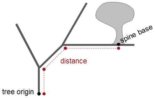
3D coordinate of the point where the spine is attached to the segment.
Reports the metrics for spines detected automatically with Neurolucida 360.
|
Each tree selected for the analysis is assigned a unique number starting at 1. |
Apparent (that is, not corrected for residual axial smear) exterior surface area of the spine in µ2. N/A: Spine is too small to determine surface area or spine was not detected in 3D. Note that when there is no correction for residual axial smear, objects typically appear elongated along the optical axis because the microscope's axial resolution is much lower than its lateral resolution. |
Shortest distance from the center of the head layer diameter to the surface of the dendrite. |
|
Uses the centrifugal branch order. |
yes: The spine head appears connected to the dendrite. no: The spine head is connected by a neck that is too dim to be identified by the image segmentation used to extract the spine shape. As a result, the spine head appears disconnected from the dendrite. To detect such a spine, you may increase the detector sensitivity and manually re-detect the spine to allow the neck to be modeled. |
Shortest distance from the center of the head layer diameter to the center of the dendrite. |
|
Refers to the classification used in Neurolucida 360 to mark the spines. |
Refers to the radius of the dendrite at the point where the spine attaches. This radius is calculated with the assumption that the dendrite is modeled as having an elliptical cross section. For a spine with a length L and an anchor radius AR, the maximum distance to the center line is: L + AR. |
Based on Rayburst diameters calculated in the XY plane after the automatic detection process. |
|
Auto: Refers to the type automatically assigned when you use Classify All. Manual: Refers to the type you assigned via the Edit Spines panel. |
Refers to the radius of the spine attachment vector with respect to the optical plane.
This is useful for discriminating between spines that are clearly visible on the side of the dendrite and spines that are detected over or under the dendritic segment when viewed in the direction of the optical axis. |
3D coordinates of the center of the head of the spine measured in microns from the reference point. |
|
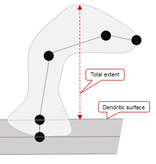
Shortest distance from the furthest identified voxel to the surface of the dendrite. To determine the radius of the dendrite, subtract Total extent from Total extent to center. |
Apparent (that is, not corrected for residual axial smear) cross-sectional area of the base of the spine (area of the dendritic model covered by the spine). N/A: Spine is too small to determine contact area. Note that when there is no correction for residual axial smear, objects typically appear elongated along the optical axis because the microscope's axial resolution is much lower than its lateral resolution. |
Shortest distance from the center of the neck layer diameter to the surface of the dendrite. |
|
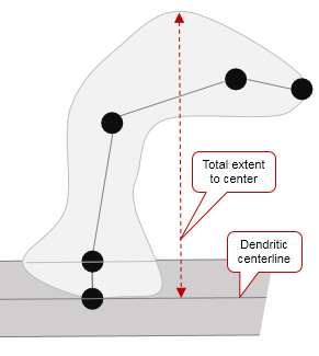
Shortest distance from the furthest identified voxel to the center of the dendrite. |
3D coordinate of the point where the spine is attached to the dendrite. |
Shortest distance from the center of the neck layer diameter to the center of the dendrite. |
|
Measured by the number of voxels that make up the spine object multiplied by the volume of a single voxel. The volume of a single voxel is: X resolution * Y resolution * Z resolution. |
Sum of the lengths of the branch segments from the base of the spine to the beginning of the tree the spine is attached to. |
Based on Rayburst diameters calculated in the XY plane after the automatic detection process. |
|
Total number of voxels that constitute the spine. Based on voxel processing and used to evaluate the spine size. It is determined by the image scaling. |
|
|
Reports the metrics for spines detected automatically with Neurolucida 360.
|
Each tree selected for the analysis is assigned a unique number starting at 1. |
Apparent (that is, not corrected for residual axial smear) exterior surface area of the spine in µ2. N/A: Spine is too small to determine surface area or spine was not detected in 3D. Note that when there is no correction for residual axial smear, objects typically appear elongated along the optical axis because the microscope's axial resolution is much lower than its lateral resolution. |
Shortest distance from the center of the head layer diameter to the surface of the dendrite. |
|
Uses the centrifugal branch order. |
yes: The spine head appears connected to the dendrite. no: The spine head is connected by a neck that is too dim to be identified by the image segmentation used to extract the spine shape. As a result, the spine head appears disconnected from the dendrite. To detect such a spine, you may increase the detector sensitivity and manually re-detect the spine to allow the neck to be modeled. |
Shortest distance from the center of the head layer diameter to the center of the dendrite. |
|
Refers to the classification used in Neurolucida 360 to mark the spines. |
Refers to the radius of the dendrite at the point where the spine attaches. This radius is calculated with the assumption that the dendrite is modeled as having an elliptical cross section. For a spine with a length L and an anchor radius AR, the maximum distance to the center line is: L + AR. |
Based on Rayburst diameters calculated in the XY plane after the automatic detection process. |
|
Auto: Refers to the type automatically assigned when you use Classify All. Manual: Refers to the type you assigned via the Edit Spines panel. |
Refers to the radius of the spine attachment vector with respect to the optical plane.
This is useful for discriminating between spines that are clearly visible on the side of the dendrite and spines that are detected over or under the dendritic segment when viewed in the direction of the optical axis. |
3D coordinates of the center of the head of the spine measured in microns from the reference point. |
|
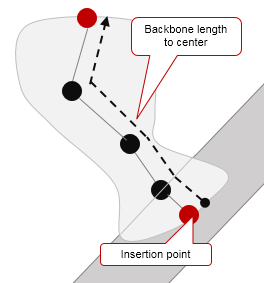
Backbone length to center minus distance between dendritic surface and insertion point on the center line. |
Apparent (that is, not corrected for residual axial smear) cross-sectional area of the base of the spine (area of the dendritic model covered by the spine). N/A: Spine is too small to determine contact area. Note that when there is no correction for residual axial smear, objects typically appear elongated along the optical axis because the microscope's axial resolution is much lower than its lateral resolution. |
Shortest distance from the center of the neck layer diameter to the surface of the dendrite. |
|
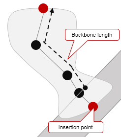
Tortuous path from furthest voxel along the path of the backbone to the insertion point on the center line. |
3D coordinate of the point where the spine is attached to the dendrite. |
Shortest distance from the center of the neck layer diameter to the center of the dendrite. |
|
Measured by the number of voxels that make up the spine object multiplied by the volume of a single voxel. The volume of a single voxel is: X resolution * Y resolution * Z resolution. |
Sum of the lengths of the branch segments from the base of the spine to the beginning of the tree the spine is attached to. |
Based on Rayburst diameters calculated in the XY plane after the automatic detection process. |
|
Total number of voxels that constitute the spine. Based on voxel processing and used to evaluate the spine size. It is determined by the image scaling. |
|
|
Neurolucida Explorer 11 | MBF Science Support Center | Downloads![]()